


System architectural design is the step in ISO 26262 that turns technical safety requirements into a structure of elements, interfaces and allocated responsibilities. Most teams draw it as a logical block diagram, and that diagram can look perfectly independent while the physical product is not. The most useful insight in architecture work is that independence is a property of the installed hardware, so it has to be checked where things are bolted down.
What is system architectural design in ISO 26262?
System architectural design defines the building blocks of an item, their boundaries, their interfaces and the requirements each one carries. It grows alongside the technical safety requirements as part of the technical safety concept, and it feeds both the hardware and software teams. ISO 26262 expects the result to be modular, granular enough to work with, and simple, because each of those properties reduces the room for systematic faults.
ISO 26262 does not fix how many diagrams to draw. Systems engineering practice separates the description into views, typically functional, logical and physical, because each view answers one question well. A functional view says what happens. A logical view says which element does it. A physical view says where the element lives, what powers it and which wires connect it. Teams tend to polish the logical view for reviews, and it is also the only view that cannot show a shared bolt.
Why can a logical block diagram hide a shared failure?
A logical block diagram hides shared failures because it draws functions, and functions do not have supply wires, connectors or ground points. A fictional active anti-roll bar shows the effect. An electric actuator twists the two halves of the front stabiliser bar. A function processor commands its torque, and a separate monitor processor compares that command with a torque sensor reading and can cut power when the two differ by more than 40 Nm.
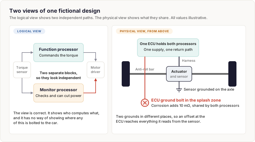
On the logical drawing, the monitor is everything a reviewer would hope for. It has its own block, its own software and its own path to the motor driver. The physical view tells a different story. Both processors sit in one electronic control unit (ECU) on the subframe, with one return path to a ground bolt in the wheel arch. The torque sensor sits on the actuator and is grounded locally at the axle.
How does a ground offset defeat an independent monitor?
A ground offset defeats an independent monitor because both processors measure the sensor against the same shifted reference. Suppose road salt adds 10 mΩ to the ECU's ground joint, and 30 A of return current from other loads on that joint flows through it. That raises the ECU's ground by 0.30 V relative to the axle, and every voltage read from the sensor appears 0.30 V too low.
The sensor scale here runs at 4 mV per newton metre, with zero torque at 2.50 V. With no torque requested, the true output of 2.50 V reads as 2.20 V, which looks like a 75 Nm error. The function processor does its job and drives the motor until its reading returns to 2.50 V. By then the sensor is really producing 2.80 V, and the bar is applying 75 Nm that nobody asked for.
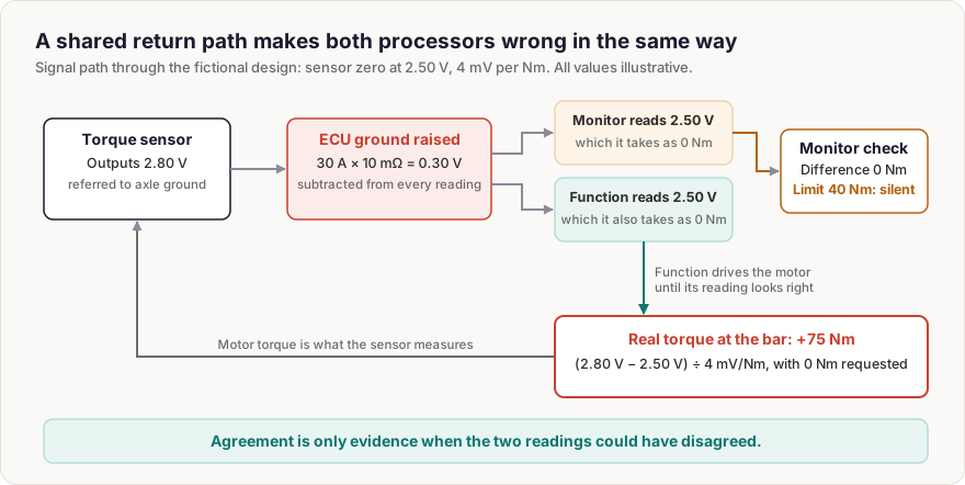
The monitor reads the same 2.50 V, believes the torque is zero and sees no difference from the request. Its 40 Nm limit is never approached, although the real error is nearly twice that. Nothing has failed in the usual sense, since both processors and all their software behave correctly, and the fault lives in a joint that appears on no logical diagram.
The physical view shows the coupling, and the analysis of dependent failures supplies the method for arguing about it. A claim of independence has to survive that analysis, which needs the physical view as input. The answer here belongs in the architecture rather than in the monitor's software: a second reference for the monitor's reading, a differential measurement or a sensor return taken back to the ECU would each make the two readings capable of disagreeing.
When should an architecture move to the physical view?
An architecture should move to the physical view early, while changing it still costs little. A ground strategy drawn after the harness is released is a change request. Drawn during concept work, it is a line on a sketch. The same goes for where a monitor is placed, which supply it uses and whether it shares a connector with the thing it monitors.
The pattern choice matters too, and safety patterns describe the options, but a pattern on paper only delivers its promise if the installation keeps the separation it assumes. A function and monitor pair drawn from a textbook can be defeated by the bolt it hangs from, as this example shows. Any ASIL attached to that pair is project-specific, and the argument for it rests on the physical facts.
The System Architectural Design and Safety Architecture concept page adds the design loop, how the three views map to each other, how to allocate requirements and numeric budgets, interface specification, measurable simplicity, a selection guide for system patterns, verifying the architecture, and a complete worked example with a review checklist.
Common questions about system architectural design
Does ISO 26262 require functional, logical and physical views?
No. It asks for elements, boundaries, interfaces and allocated requirements without prescribing diagrams. The three views are common engineering practice, because no single drawing can answer every question.
Is a monitor on a separate processor automatically independent?
No. Separate silicon removes some causes but can leave shared supply, ground, clock, inputs and installation untouched. Independence has to be argued through an analysis of dependent failures.
Can a diagnostic detect a ground offset?
Often yes, if the design provides a reference that the offset does not shift. Without such a reference, two readings shifted together will agree, and a comparison between them stays silent.
Abbreviations & Key Definitions
- ASIL: Automotive Safety Integrity Level, assigned for a specific project.
- ECU: Electronic control unit.
- Element: Any building block of an item, from a whole system down to a single part or software unit.
- Ground offset: A voltage difference between two points assumed to share the same ground.
Last updated: 11 November 2026

Comments
Loading comments