 ISO 26262Academy
A functional safety concept defines what an automotive system must do to mitigate hazards, while the technical safety concept specifies technical safety requirements and their allocation within the system architecture. This article outlines the transition from abstract safety goals to concrete architectural mechanisms, detailing how timing constraints, communication interfaces, and independence requirements shape the technical safety architecture.
Developing a robust technical architecture requires translating item-level behaviors into precise component-level constraints. Engineers must allocate safety mechanisms across microcontrollers, power supplies, and communication buses while proving that these elements operate within strict timing budgets. The resulting architecture forms the blueprint for all subsequent hardware and software development phases.
The Role of Technical Safety in the ISO 26262 Lifecycle
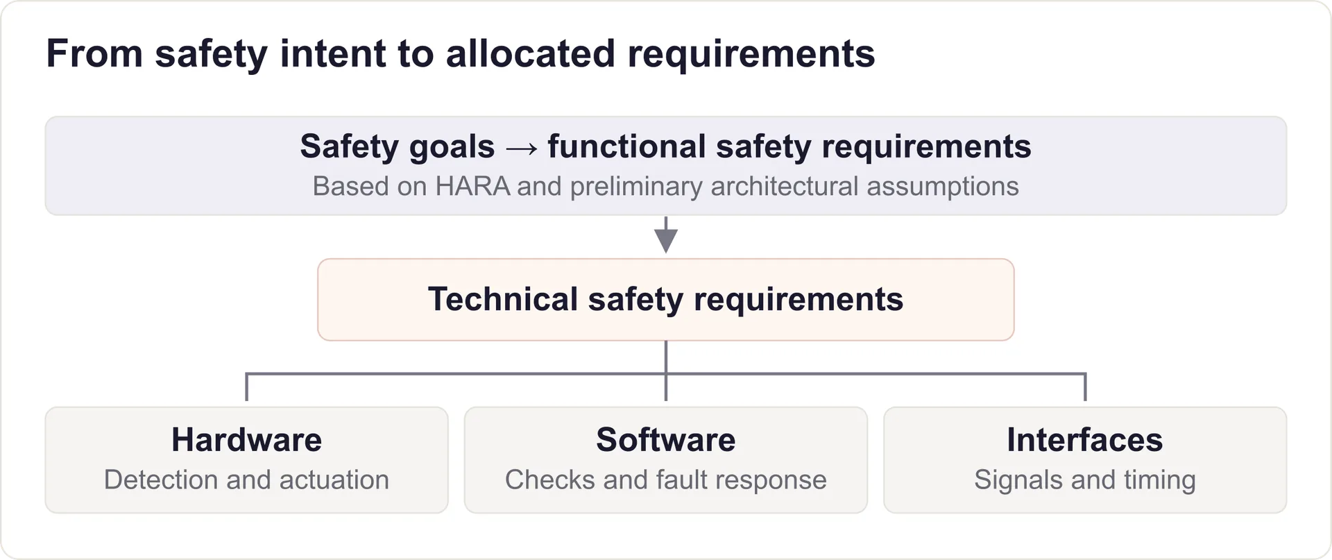
In the ISO 26262 lifecycle, the technical safety phase bridges the gap between the vehicle-level concept and the domain-specific engineering tasks. The Functional Safety Concept derives Functional Safety Requirements from safety goals and allocates them using preliminary architectural assumptions. The Technical Safety Concept takes those functional requirements and maps them to a specific system architecture.
This phase demands a deep understanding of the chosen hardware components and software execution environments. The outputs include Technical Safety Requirements, their allocation, and the system architectural design. These requirements define fault detection and control mechanisms, degradation strategies, and the safe states or emergency operation needed to prevent safety goal violations.
By explicitly allocating each requirement to either hardware, software, or a combination of both, the technical safety concept ensures that no safety-critical function is left unassigned. This allocation process also reveals potential bottlenecks in processing power, memory protection, and network bandwidth early in the design cycle.
Deriving Technical Safety Requirements
Transforming functional requirements into technical requirements requires analyzing the specific failure modes of the chosen architecture. Consider a hypothetical Adaptive Cruise Control system. A functional requirement might state that the system must prevent unintended acceleration exceeding a specific threshold. The corresponding technical requirements must define the exact mechanisms used to enforce this limit.
For this system, the technical requirements would specify a torque request plausibility check within the main microcontroller. They would define the acceptable voltage ranges for the radar sensors, the diagnostic test intervals for the analog-to-digital converters, and the exact error flags that must be set if a sensor output drifts out of bounds. The degradation logic depends on the safety concept: radar failure might require controlled ACC deactivation and a driver warning, or continued operation using a validated redundant sensing path.
Crucially, technical requirements must be verifiable. A requirement stating that a memory component must be "reliable" is invalid. For example, a RAM requirement can specify single-bit error correction and double-bit error detection per protected codeword, together with detection latency and the required response to an uncorrectable error.
Managing the Fault Tolerant Time Interval (FTTI)
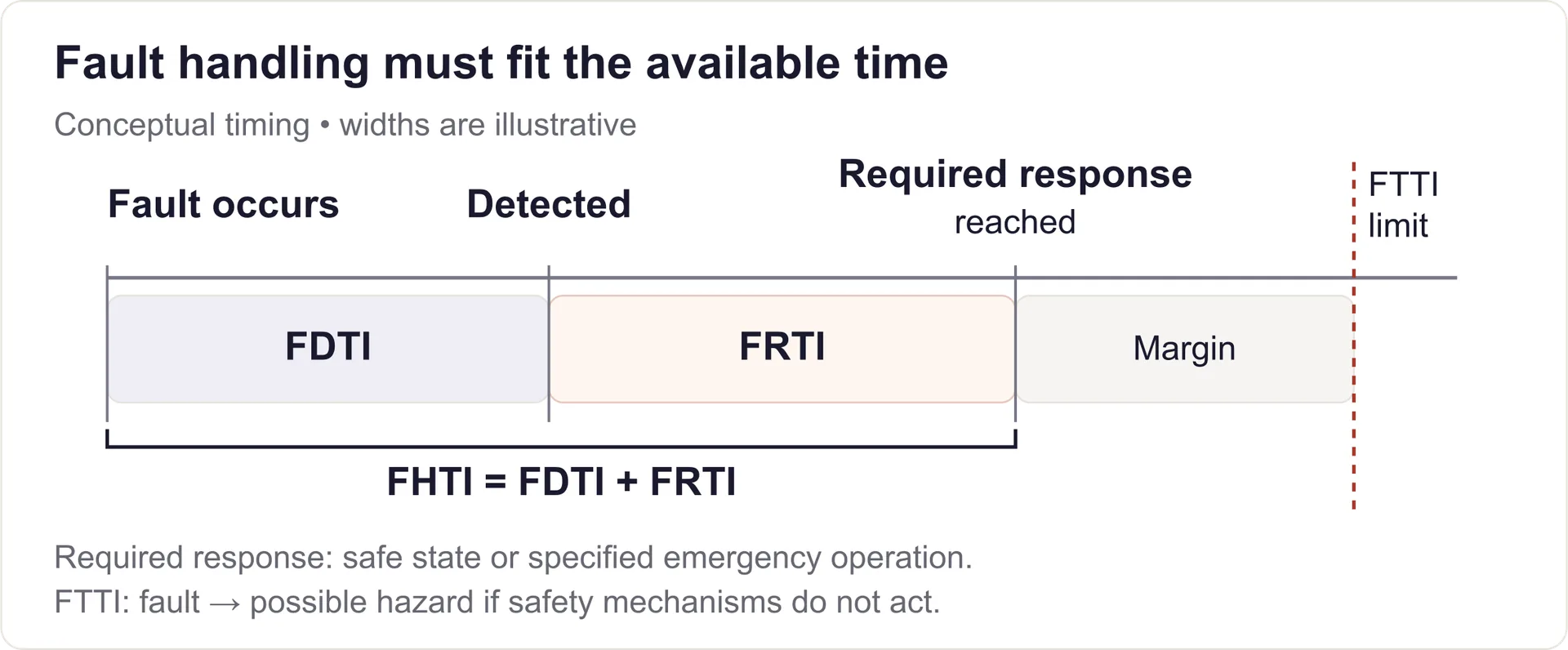
The Fault Tolerant Time Interval is a key item-level timing constraint. Defined by ISO 26262-1, it is the minimum time span from a fault occurrence in the item to a possible hazardous event if safety mechanisms are not activated. Fault handling must maintain or reach a safe state, or enter specified emergency operation, within this interval. Emergency operation has its own duration limit.
To achieve this, engineers calculate the maximum Fault Handling Time Interval. FHTI is the sum of the Fault Detection Time Interval (FDTI) and Fault Reaction Time Interval (FRTI). The detection interval runs from fault occurrence to detection, including any manifestation delay, diagnostic scheduling and debouncing. The reaction time includes the processing delay to command the safe state and the physical actuation time (such as de-energizing a relay or ramping down motor torque).
The worst-case handling time must fit within the relevant FTTI; design for FHTI < FTTI with a justified margin. If the proposed architecture cannot meet this budget, the engineering team must either select faster hardware, optimize the diagnostic software, or redesign the physical actuation path.
ASIL Decomposition in Technical Safety Architecture
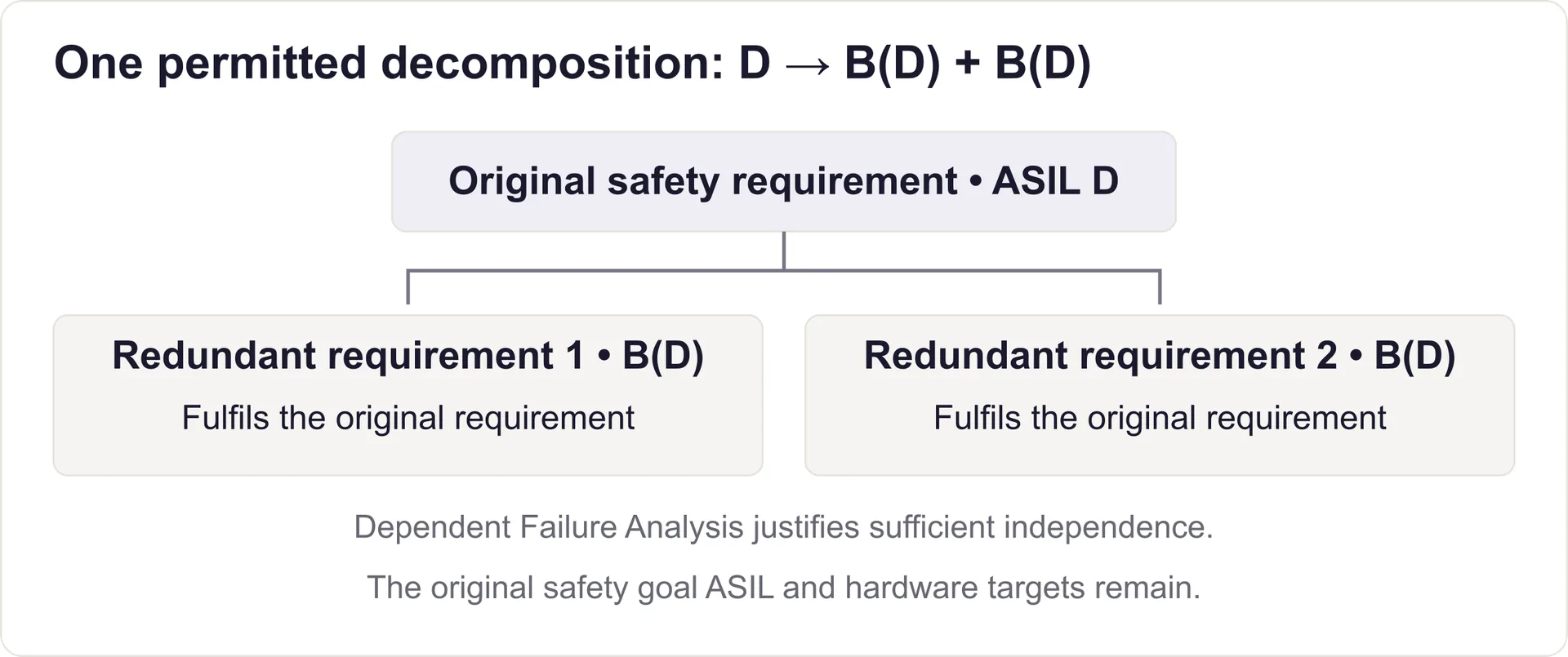
ASIL decomposition can be applied at different development levels, including technical safety concept development, to tailor the ASIL of redundant safety requirements. When a safety requirement carries a high Automotive Safety Integrity Level, developing a single complex component to that standard can be prohibitively expensive. Decomposition allocates redundant requirements to sufficiently independent elements; each must fulfil the original requirement on its own.
A common misconception is that decomposition reduces the hardware architectural metric targets for random hardware failures. This is incorrect. The safety goal retains its original ASIL. The applicable hardware architectural metrics and random hardware failure evaluation remain tied to that ASIL; decomposition does not relax those targets.
Furthermore, decomposition is only valid if the apportioned elements are sufficiently independent. Duplicating the exact same software on two identical microcontrollers does not provide independence against systematic software bugs or common-cause hardware design flaws. Dependent Failure Analysis must justify sufficient independence by addressing common-cause and cascading failures that could violate the safety requirement.
The Freedom from Interference (FFI) Mandate
Where sub-elements with different ASILs coexist, lower-ASIL or QM development requires evidence that those sub-elements cannot violate higher-ASIL requirements; otherwise the highest applicable ASIL governs their development. This principle ensures that a failure in a lower-criticality component cannot cascade and corrupt a higher-criticality function.
The software architecture must address memory, timing and execution, and exchange of information. Memory Protection Units can restrict access; scheduling and resource budgets can bound interference. Watchdogs detect selected execution faults but do not provide isolation by themselves. Communication checks and traffic controls address corrupt data and excessive bus use.
Protecting Interfaces for Technical Safety
| Communication Failure Mode | E2E Protection Mechanism | Architectural Purpose |
|---|---|---|
| Information Corruption | Cyclic Redundancy Check (CRC) | Detects covered corruption patterns; residual errors remain possible |
| Message Loss or Delay | Timeout Monitoring | Detects missing updates; application logic selects the specified response |
| Repetition or Sequence Error | Alive / Sequence Counter | Detects repetition and sequence faults within the configured profile |
| Masquerading / Addressing Error | Data ID Check | Detects message mix-ups through the expected Data ID; no sender authentication |
Interfaces are important safety boundaries. System-level development establishes the Hardware-Software Interface specification, which is refined during hardware and software development. This specification includes interrupt priorities, diagnostic register behaviors, and the precise control lines required to trigger a hardware safe state.
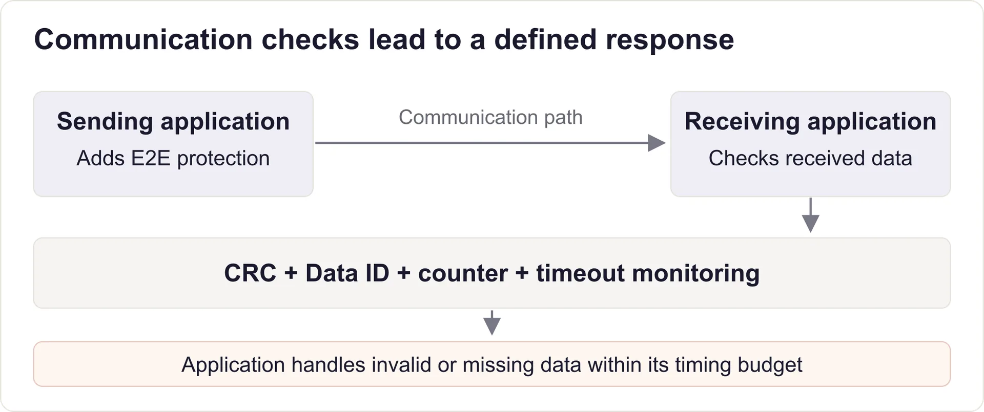
When safety-critical data crosses physical boundaries between Electronic Control Units, the communication link introduces new failure modes. ISO 26262 requires the technical architecture to protect against data corruption, message loss, unintended delays, and sequence errors. This is typically managed through End-to-End communication protection protocols.
The technical safety requirements must allocate a specific portion of the overall timing budget to the communication bus. They must also define the exact safety states the receiver should adopt if a message times out or fails its integrity check. Whether utilizing Classic CAN, CAN FD, or Automotive Ethernet, the receiver needs checks for communication integrity, sequence and timeliness. E2E safety protection does not provide cryptographic sender authentication.
Conclusion
The technical safety concept is the definitive bridge between functional intent and physical reality. Defining timing budgets, justifying independence where required, and protecting interfaces supports effective fault handling in the specified operating conditions. The concept supports ISO 26262 compliance; verification and validation must substantiate it.
Building these architectures requires a deep understanding of ASIL algebra, dependent failure analysis, and timing allocations. To master these principles and explore interactive architectural models, explore the Technical Safety Concept learning resource on ISO 26262 Academy.
Abbreviations & Key Definitions
- ASIL - Automotive Safety Integrity Level, a risk classification scheme defined by ISO 26262
- ACC - Adaptive Cruise Control, an advanced driver-assistance system that maintains a safe distance from vehicles ahead
- CAN - Controller Area Network, a robust vehicle bus standard designed for microcontrollers to communicate without a host computer
- CPU - Central Processing Unit, the primary component of a computer that acts as its "brain"
- ECC - Error-Correcting Code, a method for detecting and correcting data corruption in memory
- ECU - Electronic Control Unit, an embedded system that controls one or more of the electrical systems or subsystems in a vehicle
- E2E - End-to-End, protection that detects covered communication faults between sending and receiving applications
- FFI - Freedom from Interference, absence of cascading failures between elements that could violate a safety requirement
- FHTI - Fault Handling Time Interval, the sum of fault detection and fault reaction time intervals
- FTTI - Fault Tolerant Time Interval, minimum time from an item fault to a possible hazardous event without safety mechanisms
- HARA - Hazard Analysis and Risk Assessment, the method used to identify and categorize hazardous events
- HSI - Hardware-Software Interface, the specification defining the interaction between hardware and software elements
- MCU - Microcontroller Unit, a compact integrated circuit designed to govern a specific operation in an embedded system
- RAM - Random Access Memory, a form of computer memory that can be read and changed in any order
- SPFM - Single-Point Fault Metric, a hardware architectural metric reflecting the robustness of the item to single-point faults
- TSC - Technical Safety Concept, the specification of the technical safety requirements and system architecture
- TSR - Technical Safety Requirement, a requirement derived from the functional safety concept allocated to hardware and software
Last updated: 16 September 2026
Comments
Loading comments