 ISO 26262Academy
On a block diagram, two channels look independent. On the board they may share a regulator, a clock, a connector, a mounting position and the same compiled software. If one of those shared things fails, both channels can fail with it, and the redundancy the safety concept counted on is gone. Dependent Failure Analysis (DFA) is the ISO 26262 activity that tests whether that can happen.
Redundant is not the same as independent
Redundancy is a structural fact: there are two paths. Independence is a property that has to be argued with evidence. In ISO 26262 terms, elements are independent when no dependent failure between them can lead to a safety requirement being violated. Three kinds of claim rely on that.
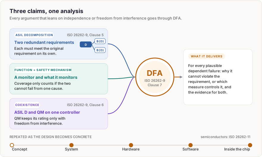
- ASIL decomposition. A requirement is split into redundant requirements with a lower ASIL, for example ASIL D into ASIL B(D) and ASIL B(D). Each must satisfy the original on its own, and the implementing elements must be sufficiently independent (ISO 26262-9:2018, Clause 5).
- A function and its safety mechanism. A monitor that shares a clock, a supply or an input with the function it supervises can fail together with it, and the coverage claimed for it is then not there.
- Coexistence. When sub-elements with different ASILs, or QM sub-elements, share one element, the lower-rated ones keep their rating only if they cannot interfere with the others (ISO 26262-9:2018, Clause 6).
The analysis itself is specified in ISO 26262-9:2018, Clause 7. It starts as soon as an independence claim exists and is repeated at system, hardware and software level as the design becomes concrete. ISO 26262-11 carries the same reasoning inside semiconductor devices.
Two ways one cause defeats two elements
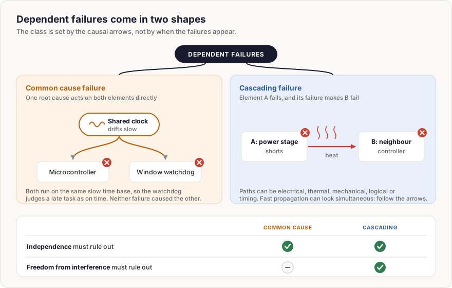
ISO 26262 recognises two kinds of dependent failure, and what separates them is the shape of the causal chain, not the timing.
A common cause failure is one root cause acting directly on two or more elements, without either causing the other to fail. Suppose a microcontroller and the window watchdog that supervises it run from the same clock source. If that clock drifts slow, both see the same wrong time base, and the watchdog can accept a task that is running late, the very error it exists to catch. The root cause can sit inside the item or outside it, and the failures need not appear at the same moment.
A cascading failure is a chain: element A fails, and its failed behaviour makes element B fail. A shorted power stage can overheat a second controller mounted beside it. A faulty node that floods a shared bus can starve a safety function of the messages it needs. Propagation can be fast enough to look simultaneous.
The split matters. Freedom from interference is about cascading failures only. Independence needs both kinds ruled out or controlled, so a freedom-from-interference argument alone does not prove independence.
Coupling factors: what ties two elements together
DFA finds dependent failures by looking for coupling factors: the shared characteristic or relationship that lets one cause reach several elements. Two channels routed through one harness branch share a coupling factor. Chafing that shorts both lines is the root cause that uses it, which ISO 26262 calls a dependent failure initiator.
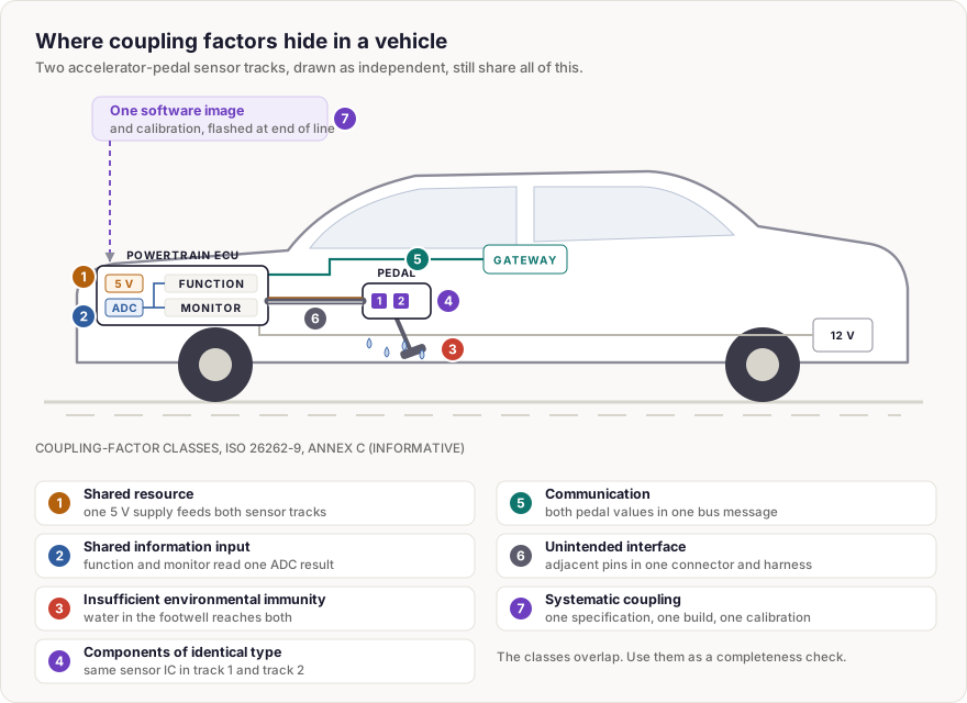
ISO 26262-9, Annex C, which is informative, lists classes of coupling factors: shared resources, shared information inputs, insufficient environmental immunity, components of identical type, communication, unintended interfaces, and systematic coupling, where one development, manufacturing, installation or service error ends up in every copy. The classes are a completeness aid, not a substitute for knowing the architecture.
Identical channels share their mistakes
The coupling factor most often missed is not on the schematic. DFA covers systematic failures as well as random hardware faults. Two identical channels built from one specification, one code base and one compiler carry the same defect. When the input that triggers it arrives, both compute the same wrong answer, and a comparator between them sees agreement. Duplication helps against random hardware faults. On its own, it does nothing against a shared design error.
Diversity helps only when it is aimed at a named cause. A second sensor using a different physical principle removes a shared weakness of the sensing element, while both sensors may still share a supply and a thermal zone. Two different part numbers may still share a die or a design block. The analysis has to show which cause the difference removes.
How DFA changes a design
DFA is mainly qualitative. For each candidate, the analyst asks whether a reasonably foreseeable cause and a working coupling path exist, and what the result would do to the safety requirement. The argument rests on architecture and evidence, not on a generic beta-factor estimate.
Where a dependent failure is plausible, the measure prevents the cause, weakens the coupling or controls the effect. That turns into concrete decisions: a separate supply for the monitor, traced back until no fuse or connector is left in common; channels in different harness branches; memory protection and execution budgets between software partitions; a diverse algorithm in the monitoring path. Found on a block diagram, a shared clock is a design choice. Found after layout, it is a board change.
Four misconceptions
- "DFA is only for ASIL decomposition." Any claim of independence or freedom from interference needs it, including the claim that a safety mechanism stays effective.
- "A thorough FMEA already covers it." An FMEA looks at one failure mode at a time. Its results are still useful input: similar parts failing in similar ways, or the same event under both inputs of an AND gate in a fault tree, show where DFA should look.
- "Software cannot have dependent failures." One task can corrupt another's memory, starve it of processor time or hand it a stale message, the three interference types of ISO 26262-6, Annex D. One compiler can put the same fault into two binaries.
- "Any shared resource fails the analysis." Sharing is not forbidden. The question is whether a plausible cause can use it to violate the requirement and, if so, whether a measure controls it.
Where to go from here
The Dependent Failure Analysis concept takes this into practice, with a coupling-factor checklist, DFA for hardware and software, lockstep processors and a worked dual-channel example.
Abbreviations
- ASIL - Automotive Safety Integrity Level, A (lowest) to D (highest).
- DFA - Dependent Failure Analysis.
- FMEA - Failure Mode and Effects Analysis.
- QM - quality management, for requirements with no ASIL.
Featured image: Tesla Autopilot HW2.5 and Infotainment Boards by Steve Jurvetson, CC BY 2.0, cropped.
Last updated: 2 October 2026

Comments
Loading comments