 ISO 26262Academy
In most safety concepts the fault tolerant time interval appears once, as a single figure in the safety goal or the functional safety requirements: "FTTI 150 ms". Then the architecture work starts, and the number is treated like a constant that someone else has already taken care of.
It is better read as a budget. Everything between the moment a fault occurs and the moment the vehicle is safe again spends from the same interval: the time to notice the fault, the time to decide, and the time for the actuators and the physics to reach the safe state. A large share of it is gone before any safety software has executed a single instruction.
What the standard actually fixes
ISO 26262-1:2018, Clause 3 defines the FTTI from the occurrence of the fault to a possible hazardous event, assuming no safety mechanism acts. Detection time also starts at the fault, not when a monitor first runs. Reaction time ends when the item reaches a safe state, or emergency operation when reaching the safe state in time is not possible. A fault only counts as handled in time when detection plus reaction stays below the FTTI.
The FTTI belongs to the item, not to an ECU. ISO 26262-3:2018, Clause 7 asks the functional safety concept to say how it is met by setting a fault handling time interval, and ISO 26262-4:2018, Clause 6 pushes a share of that interval down to each safety mechanism in the technical safety concept. That is a budget allocation in all but name.
Where 150 ms goes
A fictional electric car has a dual-track accelerator pedal sensor. One track shorts to its supply, and the pedal suddenly reads 100% while the driver is creeping forward in a queue. The vehicle control unit compares the two tracks, the safe state is zero traction torque, and the hazard analysis has given the team 150 ms before the car closes the gap to the vehicle in front.
Follow the fault through the chain. The pedal sensor's own output filter, part of the sensor supplier's design, smooths the signal for 2 ms. The pedal is sampled by a 10 ms task, so in the worst case the faulty value waits almost a full period before any code sees it. The plausibility check runs, but a single disagreement between two analogue tracks is common on a noisy harness, so the error has to be confirmed in three consecutive samples: another 20 ms. Detection is complete after about 32 ms.
Now the reaction. The zero-torque request waits for the next 10 ms bus frame and needs half a millisecond to be sent. The inverter picks it up in about 2 ms and then ramps torque down over 50 ms, because a torque step would jolt the car and can itself unsettle it. The half-shafts unwind, and torque at the wheels follows about 20 ms later. The total is 114.5 ms, inside 150 ms with 35.5 ms to spare.
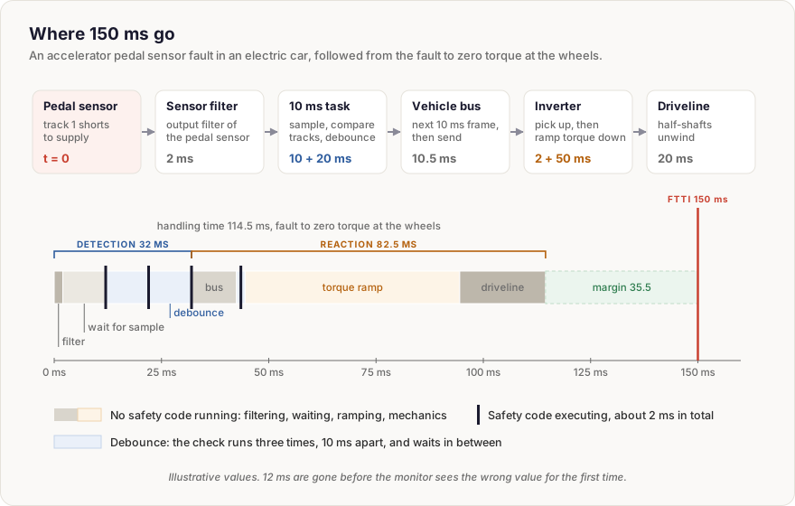
Of those 114.5 ms, the code that implements the safety mechanism executes for about 2 ms. The rest is filtering, waiting for a sample, waiting for a frame, debouncing and mechanics. Most of the interval is not spent in software, and most of it is not owned by the software team either.
Budgets drift when nobody owns them
That is why a single number in the safety goal is not enough. Every stage in the chain belongs to someone: the sensor supplier, the vehicle control unit software, the network design, the inverter supplier, the driveline engineers. Each of them can make a change that is correct in their own world and still use up the margin.
A year after the design review, the pedal sensor supplier raises its output filter from 2 to 15 ms to pass an EMC test. The inverter supplier stretches the torque ramp from 50 to 80 ms because customers complained about a clunk. No safety requirement was touched and no safety software changed. The chain now needs 157.5 ms.
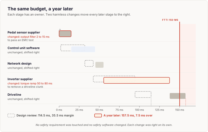
Neither change is wrong on its own. The problem is that the budget lived in a spreadsheet from the concept phase instead of in the requirements of each element. When the filter time is written into the sensor's requirements and the ramp time into the inverter's, each change triggers an impact analysis that someone will actually read. ISO 26262-5:2018, Clause 7 is explicit that a hardware safety mechanism that cannot meet the FTTI, or its allocated maximum handling time, does not count as covering the fault.
The habit worth building
Write the FTTI as an interval with line items, not a constant. Give every stage an owner and a number, including the stages where no software runs. Keep the margin visible, so that when it shrinks someone notices before the vehicle test does.
The Safety-Related Timing concept page goes further: how each interval is defined and where it comes from, how diagnostic test intervals and latent faults fit in, a fully worked timing diagram, emergency operation when the safe state is out of reach, allocation across hardware and software, how timing is verified, and the timing mistakes that most often reach an assessment.
Abbreviations & Key Definitions
- FTTI - Fault Tolerant Time Interval, from the fault to a possible hazardous event.
- FDTI - Fault Detection Time Interval, from the fault to its detection.
- FRTI - Fault Reaction Time Interval, from detection to the safe state or emergency operation.
- FHTI - Fault Handling Time Interval, FDTI plus FRTI.
- EMC - Electromagnetic Compatibility.
Last updated: 1 November 2026

Comments
Loading comments