 ISO 26262Academy
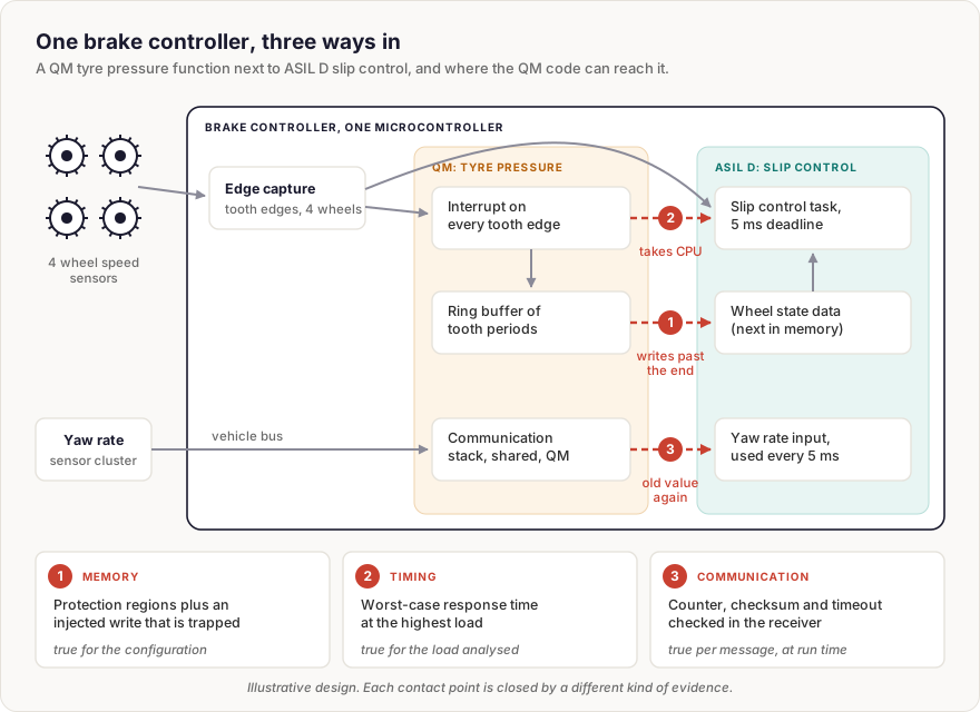
Every brake controller already measures wheel speed at each corner, so it is a natural home for indirect tyre pressure monitoring. A tyre losing pressure rolls on a slightly smaller radius and vibrates differently, and both show up in the wheel speed signals. The function is useful, it comes from a different team, and it is developed as QM. The slip control next to it, which modulates brake pressure during ABS and stability interventions, carries ASIL D.
There are only two ways for both to run on one microcontroller. Either the tyre pressure code is developed to ASIL D, which nobody wants to pay for, or the project shows that it cannot interfere with the slip control. That second route is freedom from interference, and the hard part is not the idea. It is the evidence.
What has to be shown
In ISO 26262-1:2018, Clause 3, freedom from interference means that a failure in one element cannot cascade into another and break a safety requirement. ISO 26262-9:2018, Clause 6 turns it into a rule: the QM part may stay QM only when there is evidence that it is unable to break the safety requirements, directly or indirectly. Without that evidence it inherits the highest ASIL it shares the element with. For software, ISO 26262-6:2018, Clause 7 adds that partitioning at ASIL D is backed by dedicated hardware features, a memory protection unit being the usual example, or by means shown to be equivalent, and that its effectiveness is shown during integration and verification. Equivalent has to be argued: a boundary that rests only on the QM code behaving well is not one.
The informative Annex D of Part 6 groups the faults into three kinds: memory, timing and execution, and exchange of information. Engineers tend to treat them as one item on a checklist. They are three different questions, and each one is answered by a different kind of evidence.
Memory: a property of the configuration
The tyre pressure function keeps a ring buffer of tooth periods for each wheel. An off-by-one error in the index writes one element past the end of the buffer, and the linker happened to place the slip controller's wheel state right behind it.
The evidence here is about configuration. The memory protection regions are reviewed against the linker map, and a test deliberately writes from the QM partition into ASIL D memory and shows the access trapped and the defined reaction taken. Once that holds, it holds at every vehicle speed, under every load, for every message. It has to be repeated when the memory map or the protection configuration changes, not when the driving situation does.
Timing: a property of the load
To time each wheel's rotation finely, the tyre pressure function asks for an interrupt on every tooth edge. Each interrupt is short, about 25 µs in this fictional design. But the number of edges per second grows with wheel speed. At 50 km/h the four wheels produce about 2,700 edges per second; at 250 km/h, more than 13,000. The slip control task has a 5 ms deadline, and every one of those interrupts runs ahead of it.
A memory protection unit has nothing to say about this. The tyre pressure code never touches foreign memory; it just takes processor time. The evidence has to be a worst-case response time bound for the slip control task, computed at the highest load the vehicle can produce, plus a runtime mechanism that limits or detects the interrupt rate if the bound is ever exceeded. A measurement on a test drive is only valid for the speeds that test drive reached.
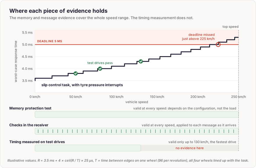
The bound comes from the usual response time recurrence: the task's own 3.5 ms plus every interrupt that can arrive before it finishes, with the edges of all four wheels lined up at the worst moment. In this example it gives 3.8 ms at 50 km/h, 4.3 ms at 130 km/h, and passes 5 ms just above 225 km/h. Every test drive passed, and the vehicle's top speed is 250 km/h.
Communication: a property of each message
The slip control also needs the yaw rate, which arrives over the vehicle bus from a sensor cluster. On its way in, it passes through a communication stack that the tyre pressure function uses too, and which was developed as QM. If that stack hands over the previous value a second time, the slip control acts on a yaw rate that is 10 ms old and believes it is current.
No configuration review and no load analysis catches a single stale message. The evidence is a check inside the ASIL D receiver that rejects data which is repeated, corrupted or late, typically a counter, a checksum and a timeout, and tests that inject exactly those faults and show the slip control reacting as specified. It works one message at a time, at run time, whatever happened in the stack.
Three arguments, not one
The mistake is to treat an argument for one kind of interference as cover for the other two. A clean memory protection test says nothing about processor time, and a response time bound says nothing about a stale value. The coexistence claim stands only when each kind has evidence of its own type: configuration for memory, worst-case load for timing, and per-message checks for communication.
The Freedom from Interference concept page covers the full fault model behind each kind, the analysis methods, the techniques and how they are verified, three complete worked examples, the tool support, and the challenges that come up when these arguments are assessed.
Abbreviations & Key Definitions
- QM - Quality Management, no ASIL assigned.
- ASIL - Automotive Safety Integrity Level, A to D.
- Coexistence - Elements with different ASILs, or none, running in one element, each keeping its own ASIL because interference is ruled out.
Last updated: 1 November 2026


Comments
Loading comments