 ISO 26262Academy
Ask a hardware engineer how often a component fails and you get a number, in FIT, with a mission profile behind it. Ask the same question about the software in a brake controller and there is no number to give. ISO 26262 does not pretend otherwise. That one gap shapes how the standard treats software, and it explains most of what Part 6 asks a team to produce.
A fault that is already there
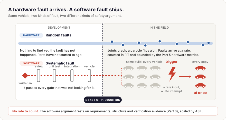
A software fault is written in, not worn in. It arrives with a requirement that was read two ways, a boundary case nobody specified, or an interrupt that runs later than the design assumed. From that commit on, it ships in every vehicle that carries the build. It does nothing until the input or timing that triggers it turns up, possibly years after start of production, and then it can turn up across a whole fleet at once.
That is why the standard classes software faults as systematic. Hardware gets two treatments: process measures for its systematic faults, and quantitative targets for its random ones, the single-point and latent fault metrics and the probabilistic metric for random hardware failures in Part 5. Software gets only the first. With no failure rate for a function, there is no software row in an FMEDA, and the safety argument has to rest on something else: requirements that can be verified, a structure that contains faults, and verification evidence whose depth rises with the ASIL.
Software plays two parts in the same safety case
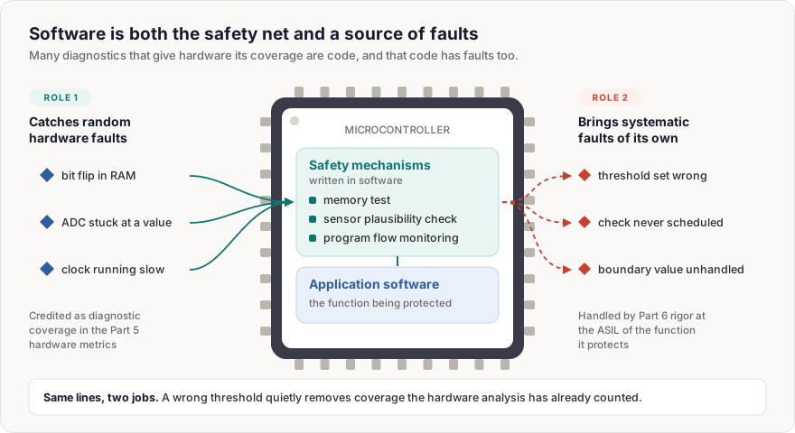
This is where software stops being one discipline among several and becomes central. Many of the diagnostics that give hardware its coverage are executed by software. A memory test, a plausibility check between two sensors, a check that the control task ran in the expected order: the hardware metrics credit them, and they are code.
So the same lines do two jobs. They are the mechanism that detects random hardware faults, and they are a possible source of systematic faults of their own. A plausibility check with the wrong threshold is a systematic fault that quietly removes coverage the hardware analysis has already counted. Whoever writes a safety mechanism is carrying two sets of obligations at once: the coverage the hardware analysis assumed, and the Part 6 rigor that comes with the ASIL of the function being protected.
One controller, many criticalities
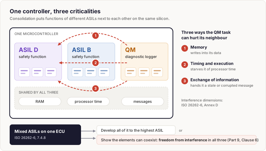
The second shift is consolidation. A function used to own its ECU. Domain and zonal controllers now run a braking-related function, a comfort feature and a diagnostic logger on one microcontroller, sometimes on one core. Software is what makes that sharing possible, and software is what makes it risky.
ISO 26262-6, 7.4.8 sets the rule. When embedded software mixes components with different ASILs, or puts QM code next to safety-related code, all of it is treated at the highest ASIL present, unless the components meet the coexistence criteria in ISO 26262-9, Clause 6. Nobody wants to develop a logging task to ASIL D, so in practice the work becomes an argument for freedom from interference. Annex D of Part 6 frames that argument in three dimensions: memory, timing and execution, and exchange of information. The QM task must not be able to write into the ASIL task's data, starve it of processor time, or hand it a stale or corrupted message that it then trusts.
Naming the three dimensions is the easy part. Showing that the memory protection covers every write path, that the timing budget holds under worst-case load, and that the communication protection detects the faults it claims to, is where architecture reviews spend most of their time.
Part 6 converges on the software architecture
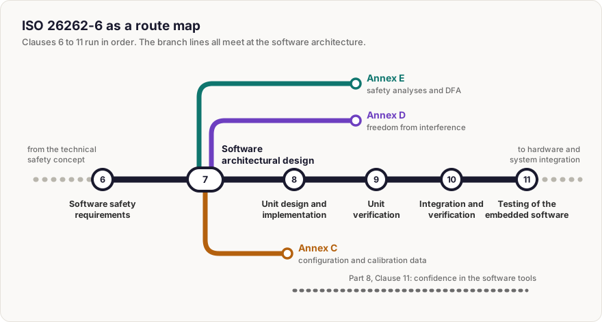
Read Part 6 in order and it looks like a development process: software safety requirements in Clause 6, architectural design in Clause 7, unit design and implementation in Clause 8, unit verification in Clause 9, integration and verification in Clause 10, and testing of the embedded software in Clause 11. Read it for where the decisions are made and the weight moves to Clause 7. The architecture is where a requirement is allocated to a component, where the partitioning that carries the interference argument is chosen, and where the safety analyses and dependent failure analyses described in Annex E are run against the design rather than against finished code.
Unit design works at the other end of the scale. Its job is to keep each unit small, simple and precisely defined at its interfaces, so that the verification Clause 9 asks for is actually achievable. The method tables leave no doubt that expected rigor rises with the ASIL. A unit that is awkward to test at ASIL A becomes a schedule problem at ASIL D.
The code is not the only software
Some of the safety weight sits in places that do not look like code. Configuration and calibration data are covered by Annex C of Part 6, which is normative: a parameter that can switch a monitor off or move a threshold carries the ASIL of the software it configures. The compiler, code generator and static analyser that turn a design into a binary need their own confidence argument under ISO 26262-8, Clause 11, because an error they introduce is a systematic fault that nobody wrote.
And software keeps changing after the vehicle is sold. Every update reopens the question the original release answered: what does this change touch, and what has to be verified again? A team answers that in days only if the traceability from safety goal to unit was built in from the start rather than reconstructed for the assessment.
Where to go from here
This article stops at the shape of each problem. The Software Architectural & Unit Design concept page goes the rest of the way. Across eleven chapters it derives software safety requirements and traces them down to units, sets out the design principles and patterns the standard expects, shows how an AUTOSAR stack carries the safety mechanisms, argues freedom from interference on multicore controllers, applies dependent failure analysis to mixed-criticality software, and works through unit design rules and case studies on real automotive functions.
Last updated: 1 October 2026

Comments
Loading comments