 ISO 26262Academy
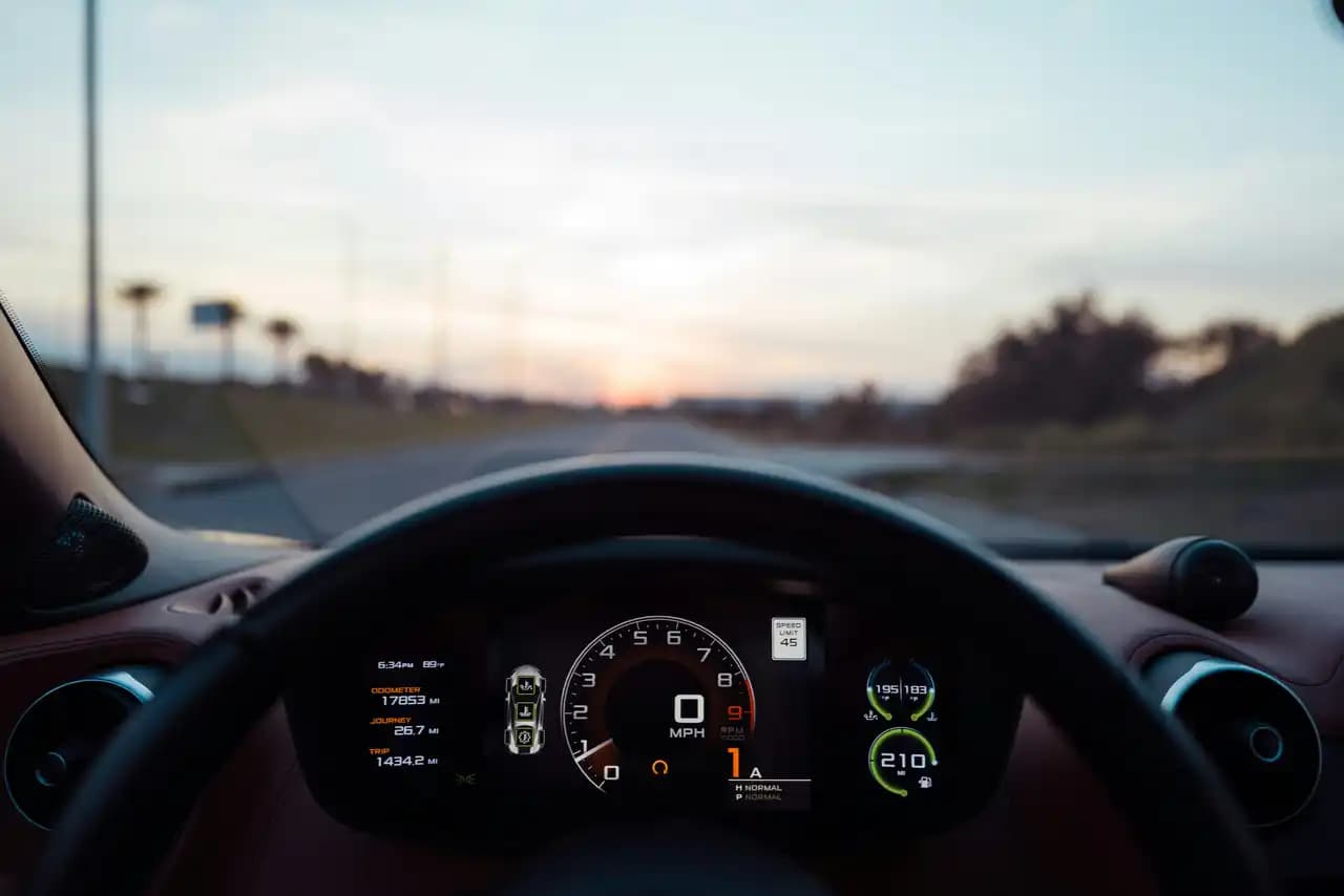
Imagine you are driving down a highway at 120 kilometers per hour. Suddenly, a fault occurs in the Electronic Power Steering (EPS) system, resulting in a sudden loss of steering assist. If the digital instrument cluster freezes or fails to illuminate the steering warning tell-tale, you remain completely oblivious to the failure until you attempt to change lanes. By the time you realize the steering wheel is heavy, it might be too late to execute a safe maneuver.
In modern automotive engineering, Human-Machine Interface (HMI) and display systems are far more than just user experience features. They act as critical safety mechanisms. When a primary vehicle system degrades, the warning path becomes the absolute final line of defense. Relying on a human response is a perfectly valid strategy under ISO 26262, but it requires rigorous engineering, precise timing budgets, and highly reliable rendering pipelines.
The Driver as an Active Safety Mechanism
Most functional safety concepts focus heavily on silicon and software implementations. Engineers implement hardware watchdogs, lockstep processing cores, and redundant sensors to detect and mitigate faults automatically. However, many systems also rely on an expected, physical response from the driver to maintain safety.
Controllability and the HARA
During the Hazard Analysis and Risk Assessment (HARA), safety engineers evaluate every potential hazardous event using three distinct parameters. These include Severity of the potential harm, Exposure to the specific driving situation, and Controllability. Controllability defines the ability of the driver or other road users to avoid the harm once a malfunction occurs.
If your functional safety concept claims a high level of controllability, you must guarantee that the driver receives a timely, unmistakable warning. ISO 26262 does not leave driver warnings solely to the discretion of interaction designers. A formal warning and degradation strategy is strictly required. This strategy forms a degradation ladder, trading full functionality for fault tolerance. It steps down through degraded states until a safe state or a predefined emergency operation is reached, ensuring the driver is informed at every critical transition.
Managing Warning Chaos: Escalation and Arbitration
When a primary vehicle system fails, it often triggers a cascade of secondary faults across the network. Without a carefully defined arbitration strategy, the digital cluster can easily overwhelm the driver with simultaneous, conflicting alerts. This overload can startle the driver into an unsafe physical response.
A robust warning manager must implement a strict priority scheme to handle these scenarios. Consider these three foundational rules for warning arbitration:
- Priority by consequence: Always derive warning priority from the potential consequence and the required driver action. Do not prioritize based on which message arrived first over the vehicle network.
- Suppress descendants, keep the root: If an underlying fault causes multiple subsystem failures, consolidate the explanatory messages. However, you must ensure that legally required tell-tales and the highest-priority action instructions remain highly visible.
- Rotate what must coexist: Regional regulations often dictate special behavior for tell-tales that share a common physical space on the display. Apply these exact activation and coexistence rules rather than inventing custom logic for every new message.
The Race Against Time: FTTI and Warning Budgets
A warning that arrives after a hazard window closes is entirely useless. Timing is critical in functional safety, and you must budget every millisecond of the fault response path.
The Fault Tolerant Time Interval (FTTI) starts the exact moment a fault occurs. It ends at the earliest possible hazardous event if no safety mechanism intervenes. To maintain safety, the Fault Handling Time Interval (FHTI) must be shorter than the FTTI.
When you rely on a driver warning, the human reaction time becomes a massive consumer of your safety budget. Consider a direct warning-and-action path for our earlier EPS failure scenario:
- Fault Detection Time Interval (FDTI): The steering system takes 100 milliseconds to detect the loss of motor assist.
- Warning Generation: The network transmission, graphics rendering, and display scan-out consume another 150 milliseconds.
- Human Reaction Time: You allocate 2.0 seconds for the driver to perceive the visual warning and grip the steering wheel firmly.
- System Response: The mechanical transition and vehicle stabilization take 250 milliseconds.
In this scenario, the total consumed time is 2.5 seconds. If the vehicle-level FTTI is 3.5 seconds, you have a defensible safety concept with 1.0 second of architectural headroom. However, you cannot simply guess this human reaction allowance. You must back up that 2.0-second assumption with representative evidence, human factors research, and clear acceptance criteria.
The Digital Cluster Trust Problem: From Bulbs to Pixels
| Fault Condition | Tell-Tale State | Failure Mode | Safety Implication |
|---|---|---|---|
| Present | ON | None (Correct) | Driver is properly informed. |
| Absent | ON | False Alarm (False-On) | Cry-wolf erosion, unnecessary panic or braking. |
| Absent | DARK | None (Correct) | Normal driving operation continues. |
| Present | DARK | Dangerous Silence (False-Off) | Driver is entirely unaware of a critical fault. |
In the past, a warning light was a simple incandescent bulb hardwired directly to a physical sensor. Today, a modern cockpit domain controller is a powerful computer running a highly complex graphics subsystem.
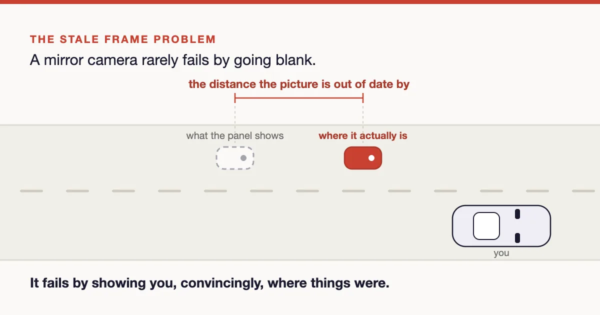
Vehicle data arrives via automotive networks. An HMI application decides what to display, a graphics stack converts this into workload instructions, and a compositor merges the various visual layers. Finally, a display controller sends the image out through a high-speed serial link to the panel. Every single step in this digital rendering pipeline is an opportunity for the truth to be lost or corrupted.
Because modern System on Chip (SoC) architectures share CPU cores, memory, and physical screens between rich infotainment and safety-critical functions, establishing freedom from interference is paramount. Even if software partitions are perfectly isolated by a hypervisor, they still feed into a single hardware compositor and a single piece of glass. You must guarantee that the safety warning layer always renders on top, even if the infotainment system experiences a catastrophic software crash.
The Two Ways a Tell-Tale Can Lie
When analyzing display safety, a tell-tale generally fails in one of two directions. These failures are not symmetric in their safety implications:
- False Alarm (False-On): The display shows a warning when no fault actually exists. While this can cause unnecessary panic, sudden braking, or frustrating workshop visits, its ultimate safety consequence depends entirely on the required action and the surrounding driving situation.
- Dangerous Silence (False-Off): A genuine fault occurs in the vehicle, but the display remains completely dark. This is often the most critical failure mode because it actively deprives the driver of the necessary information to take corrective, life-saving action.
Designing safety-critical HMI systems requires a deep understanding of human factors, precise timing budgets, and complex digital rendering pipelines. You cannot simply trust the pixels on a screen; you must engineer and verify the entire warning path to meet rigorous ISO 26262 standards.
Ready to elevate your functional safety expertise? Dive deeper into rendering pipelines, timing budgets, and compliance strategies with our comprehensive HMI & Display Safety course on the ISO 26262 Academy platform, or test your knowledge with our free practice exams today!
Abbreviations & Key Definitions
- CAN - Controller Area Network, a robust vehicle bus standard designed to allow microcontrollers and devices to communicate.
- EPS - Electronic Power Steering, a system that uses an electric motor to assist the driver in steering the vehicle.
- FDTI - Fault Detection Time Interval, how long it takes for a fault to be noticed after it appears.
- FHTI - Fault Handling Time Interval, the total time to notice a fault and bring the system to a safe state.
- FTTI - Fault Tolerant Time Interval, the time budget between a fault appearing and the earliest moment it could lead to a hazardous event if nothing reacts.
- GPU - Graphics Processing Unit, a specialized electronic circuit designed to rapidly manipulate memory to accelerate image creation.
- HARA - Hazard Analysis and Risk Assessment, the analysis that finds what could go wrong at vehicle level and rates each risk.
- HMI - Human-Machine Interface, the dashboard, screens, and controls through which the driver interacts with the vehicle.
- SoC - System on Chip, an integrated circuit that integrates all or most components of a computer or other electronic system.
Last updated: 18 October 2026

Comments
Loading comments