 ISO 26262Academy
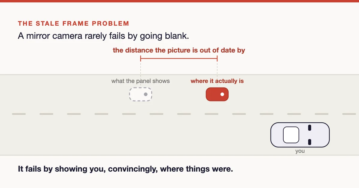
Two of the cameras on a modern vehicle are not there to see the road ahead. One replaces the exterior mirrors. The other watches the driver. Neither feeds trajectory control, and both fail the same awkward way: they carry on producing a plausible picture.
Two cameras, two different loops
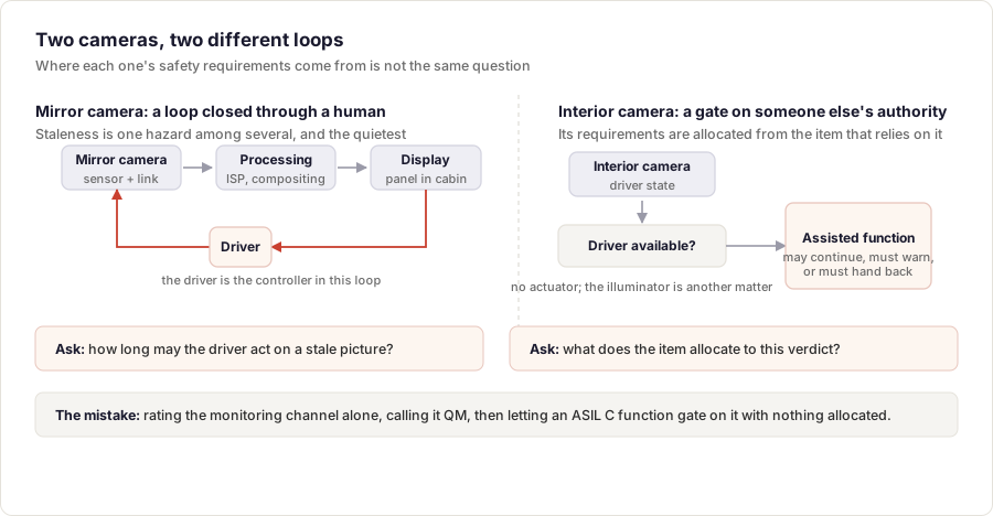
A camera monitor system replaces a mirror, so its loop closes through a human: sensor, link, processing, display, the driver's eyes and hands. The driver is the controller, which gives one family of its hazards a time dimension: a picture that has stopped advancing is dangerous in a way that is invisible to the person looking at it. A mirrored view, a wrong crop or a dazzling panel are hazardous on their own terms. Staleness is the one this article follows, because it is the one the obvious mechanisms miss.
An interior camera does two jobs that are easily confused. One is a mandated warning function in its own right. The other is quieter: an assessment of the driver that another function consults before deciding whether it may keep driving. In that second role it is a gate on somebody else's authority. As an information source it has no actuator, though its near-infrared illuminator does: a stuck-on emitter is a photobiological hazard of its own.
That second role is where the ASIL argument goes wrong. The hazardous event is not "the monitoring channel was wrong". It is an assisted function that carried on driving because it had been told the driver was available. That event is classified in the HARA of the item containing the function; the safety goal carries the ASIL; requirements derived from it keep that ASIL and are allocated to the monitoring function and to the interface carrying its verdict. Reducing the ASIL on the monitoring side is decomposition, with independence to demonstrate, not something that follows from rating the camera alone.
What the type approval already fixed
Both arrive with regulatory requirements attached. UN R46 has allowed camera monitor systems to replace mirror classes I to IV since 2016, bounds system latency below 200 ms, and lets the update rate fall to 15 Hz in low light, so the minimum rate, not the nominal one, is what your timing analysis must survive. ISO 16505 supplies the test procedures, and R46's Annex 12 asks for a safety concept over a failure list that includes frozen image content. On the interior side the EU General Safety Regulation mandates drowsiness warning through Delegated Regulation (EU) 2021/1341 and distraction warning through (EU) 2023/2590, for all new vehicles from 7 July 2024 and 7 July 2026, under a closed-loop data condition: only what the system needs, never available to third parties, deleted immediately after processing. None of it gives you a failure rate, an ASIL or an independence requirement, so trace it as regulatory: a type-approval number should not quietly acquire an ASIL it was never derived for.
The failure that shapes the architecture
Ask a camera chain whether the data arrived intact and it answers confidently. Ask whether the picture is current and most of its mechanisms have nothing to say. A link CRC detects transmission corruption between its two ends and cannot tell you when the pixels were captured. A register readback proves the sensor is configured, not that it is exposing. A watchdog proves the imaging task is scheduled, and a task republishing its last buffer is scheduled perfectly. So a frame can pass every check and still show a moment that has passed, whether the sensor stopped streaming, the display controller is holding its framebuffer, or a timing controller froze with a good image latched in it.
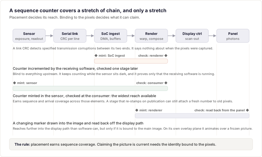
The usual answer is a frame counter, and where you put it decides most of what it is worth. A counter is evidence about the chain between where it is minted and where it is checked. Increment it in the software that receives frames and you have proved only that this software is running: it keeps counting while the sensor sits dark. Mint upstream of what you want to detect, check downstream of it, and expect no credit outside that interval.
Then the part that gets skipped. A counter is metadata: it travels next to the pixels, not inside them. A stage that re-stamps on publication rather than carrying source identity through can attach a fresh number to old pixels, and a header-only check will pass it. Good placement earns sequence and arrival coverage. Claiming the picture is current is a stronger claim, needing the identity bound to the pixel content through every transformation.
The interval nobody measures
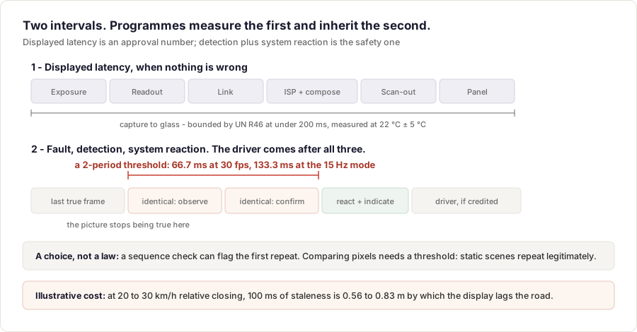
Programmes measure glass-to-glass latency because the approval asks for it. The chain that decides whether the concept works is a different one, worth keeping in parts: the fault occurs, a mechanism detects it, the system reacts and indicates, and only then, and only where controllability credits it, does the driver act. Detection plus system reaction is the part you own, and the part that must fit inside the fault tolerant time interval.
At 30 fps a frame period is 33.3 ms, and what detection costs depends on the mechanism rather than on freeze detection as a category. A sequence check can flag the first repeat. Comparing pixel content needs a threshold, because static scenes repeat legitimately and no fixed number of identical frames ever proves a freeze. Set that threshold at two periods and it costs 66.7 ms at 30 fps, 133.3 ms in the 15 Hz mode. At an illustrative 20 to 30 km/h of relative closing, 100 ms of staleness is 0.56 to 0.83 m by which the display lags the road.
The same output, from two different worlds
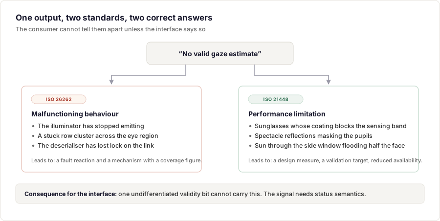
A monitoring channel reports no valid gaze estimate. A failed illuminator or a stuck row cluster across the eye region is malfunctioning behaviour: ISO 26262, with a failure rate and a mechanism you can put a coverage figure against. Sunglasses whose coating blocks the sensing band, a reflection masking the pupils, low sun flooding half the face: the hardware is healthy. Those are triggering conditions, ISO 21448, leading to a design measure and a validation target.
Either way the consumer sees the same output, which lands on the interface. A scalar estimate plus one undifferentiated validity bit cannot carry the difference. The signal needs status semantics separating "faulted" from "cannot see well enough right now", and the consumer has to act on the two differently.
Where to go next
Two decisions carry most of the weight. Derive the interior camera's requirements from the item whose function relies on its verdict, not from rating the camera alone. And treat the mirror camera as a control loop with a human in it, so the analysis produces intervals rather than only image quality.
The full treatment, with the fault catalogue, the hardware metrics, the safe-state ladder and a worked example, is in the Interior and Mirror Cameras concept.
Last updated: 12 October 2026
Comments
Loading comments